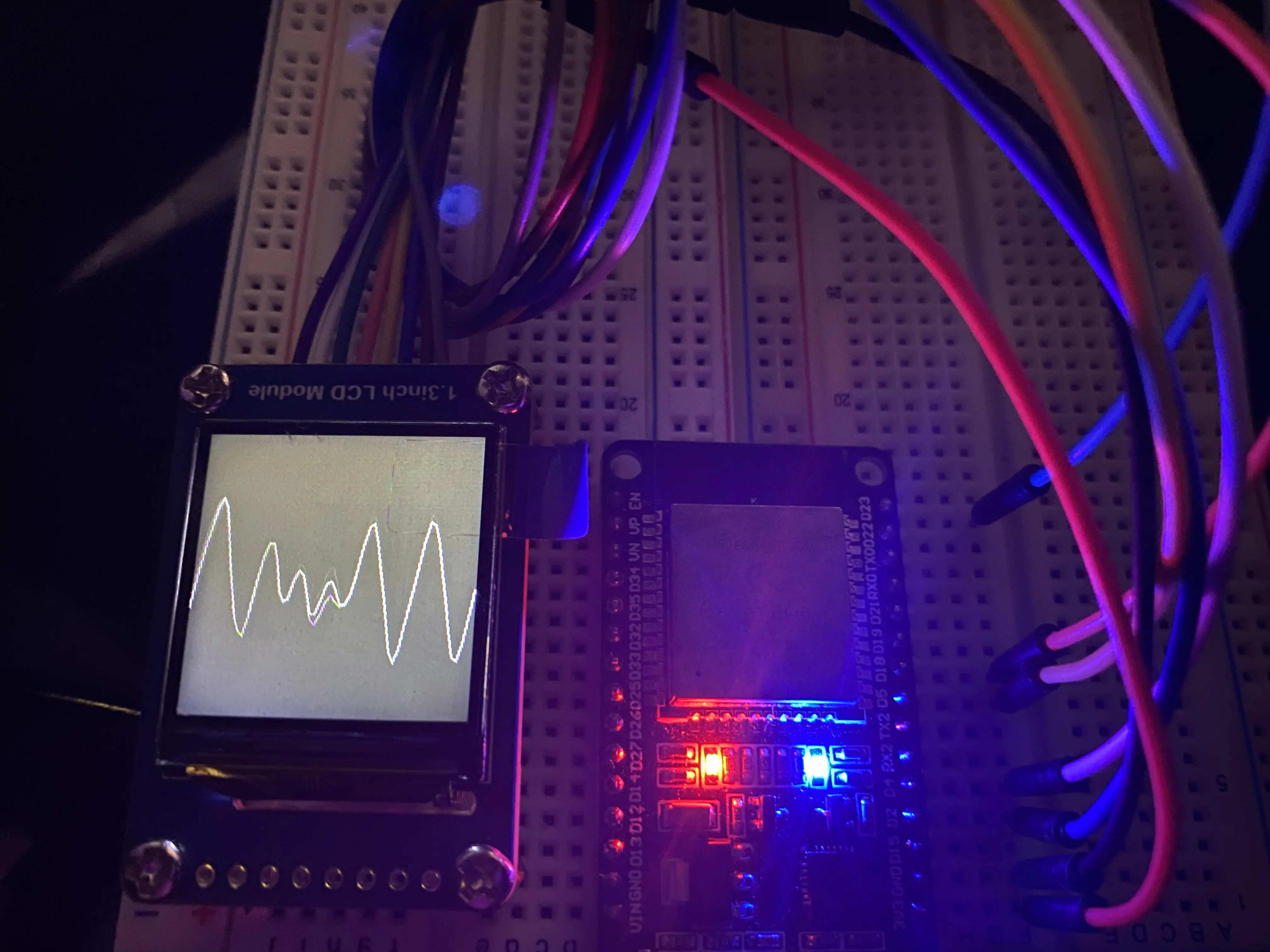
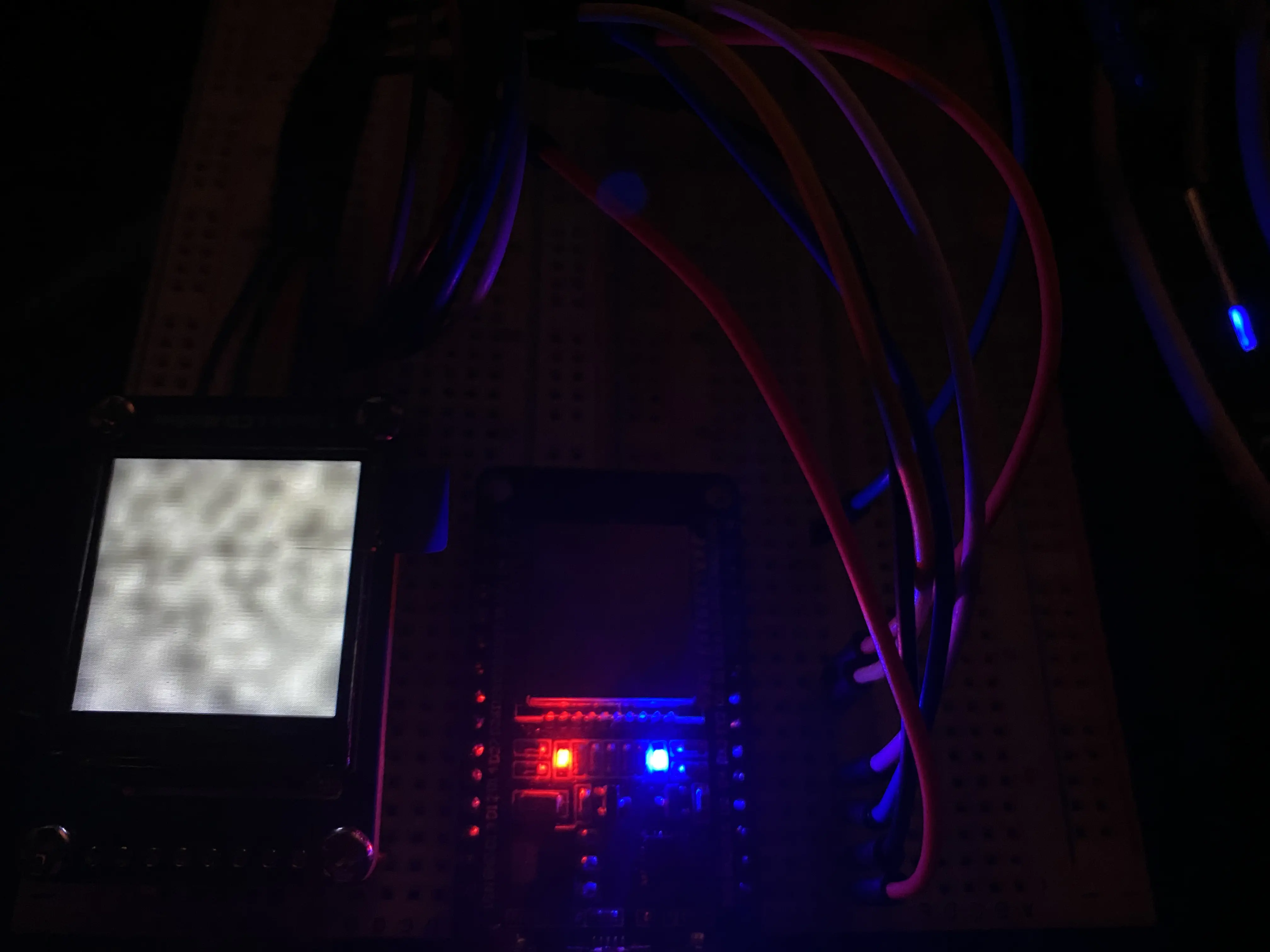
ESP32 から WaveShare 15867 1.3インチ 240×240 IPS LCD モジュールを使ったのでメモ。
また、LCDにはパーリンノイズで生成したグラフィックスを表示した。
この記事にはIPSとIPSという言葉が出てきます。
IPSは液晶ディスプレイの一形式で、
SPIはコンピュータ内部で使われるデバイス同士を接続するバスです。
- https://ja.wikipedia.org/wiki/IPS%E6%96%B9%E5%BC%8F
- https://ja.wikipedia.org/wiki/%E3%82%B7%E3%83%AA%E3%82%A2%E3%83%AB%E3%83%BB%E3%83%9A%E3%83%AA%E3%83%95%E3%82%A7%E3%83%A9%E3%83%AB%E3%83%BB%E3%82%A4%E3%83%B3%E3%82%BF%E3%83%95%E3%82%A7%E3%83%BC%E3%82%B9
配線
個人的には、 こちらと こちらを 参考にさせていただいたらSPIの理解が捗りました。
SPIで使用するピンの名称
| Arduino | Master側 | Slave側 | 別名 | 用途 |
|---|---|---|---|---|
| SCK | SCK | SCK | SCLK, SCL | データ送信のクロックをマスターが送信する |
| MISO | SDI | SDO | DC, D/C | マスターの受信、スレーブの送信をする |
| MOSI | SDO | SDI | SDA | マスターの送信、スレーブの受信をする |
| SS | SS | CS | 特定スレーブのCSを0Vにすることで通信先を選択する |
Arduino UNO(or ESP32)とLCDモジュールの配線
| TFT LCD | ESP32 | Arduino Uno | 説明 |
|---|---|---|---|
| BL | 未接続 | 未接続 | バックライト制御 |
| CS | 5 | 10 | チップセレクト |
| DC | 2 | 8 | データ/コマンド制御(MISO) |
| RES | 4 | 9 | リセット信号入力 |
| SDA | 23 | 11 | シリアルデータ入力(MOSI) |
| SCL | 18 | 13 | シリアルクロック |
| VCC | 3.3V | 5V | 電源 |
| GND | GND | GND | Ground |
二次元パーリンノイズ
パーリンノイズには、FastLEDを使用した。

#include <Adafruit_GFX.h>     // Core graphics library
#include <Adafruit_ST7789.h>  // Hardware-specific library for ST7789
#include <SPI.h>
#include <FastLED.h>

#if defined(ESP32)
    #define TFT_RST 4
    #define TFT_DC 2
    #define TFT_CS 5
#else
    #define TFT_CS 10
    #define TFT_RST 9
    #define TFT_DC 8
#endif

Adafruit_ST7789 tft = Adafruit_ST7789(TFT_CS, TFT_DC, TFT_RST);

int gridSize;
int loopCount = 0;

void setup(void) {
  Serial.begin(9600);
  Serial.print(F("Hello! ST77xx TFT Test"));
  tft.init(240, 240);
  Serial.println(F("Initialized"));

  uint16_t time = millis();
  tft.fillScreen(ST77XX_BLACK);
  time = millis() - time;

  Serial.println(time, DEC);
  delay(500);

  gridSize = tft.width() / 60;
}

void loop() {
  tft.fillScreen(ST77XX_BLACK);

  tft.startWrite();
  for (int x = 0; x < tft.width() / gridSize; x++) {
    uint8_t n1 = inoise8(
      (x * gridSize) * 10,
      loopCount * 20);
    uint8_t y1 = map(n1, 0, 0xFF, 0, 240);
    uint8_t n2 = inoise8(
      ((x + 1) * gridSize) * 10,
      loopCount * 20);
    uint8_t y2 = map(n2, 0, 0xFF, 0, 240);
    tft.writeLine(x * gridSize, y1,
                  (x + 1) * gridSize, y2,
                  ST77XX_WHITE);
  }
  tft.endWrite();
  loopCount++;
}
三次元パーリンノイズ

#include <Adafruit_GFX.h>     // Core graphics library
#include <Adafruit_ST7789.h>  // Hardware-specific library for ST7789
#include <SPI.h>
#include <FastLED.h>

#if defined(ESP32)
    #define TFT_RST 4
    #define TFT_DC 2
    #define TFT_CS 5
#else
    #define TFT_CS 10
    #define TFT_RST 9
    #define TFT_DC 8
#endif

Adafruit_ST7789 tft = Adafruit_ST7789(TFT_CS, TFT_DC, TFT_RST);

int gridSize;
int loopCount = 0;

void setup(void) {
  Serial.begin(9600);
  Serial.print(F("Hello! ST77xx TFT Test"));
  tft.init(240, 240);
  Serial.println(F("Initialized"));

  uint16_t time = millis();
  tft.fillScreen(ST77XX_BLACK);
  time = millis() - time;

  Serial.println(time, DEC);
  delay(500);

  gridSize = tft.width() / 60;
}

void loop() {
  for (int y = 0; y < tft.height() / gridSize; y++) {
    for (int x = 0; x < tft.width() / gridSize; x++) {
      uint8_t n = inoise8(
        (x * gridSize) * 10,
        (y * gridSize) * 10,
        loopCount * 20
      );
      uint8_t r = map(n, 0, 0b11111111, 0, 0b00011111);
      uint8_t g = map(n, 0, 0b11111111, 0, 0b00111111);
      uint8_t b = map(n, 0, 0b11111111, 0, 0b00011111);
      uint16_t color = (r << (5 + 6)) + (g << (5)) + (b);
      tft.fillRect(x * gridSize, y * gridSize, gridSize, gridSize, color);
    }
  }
  loopCount++;
}
二次元とほとんど変わらないけど、 白黒だけではなく、グレースケールの濃淡を表示する必要がある。 なので、ピクセルの色を以下のように16bitのRGB値で表現する必要がある。 16bitカラーでは、Rが5bit、Bが6bit、Bが5bitで表現されるので、 それぞれの値をマップし、ビットシフトすることで16bitカラーを計算した。
uint8_t r = map(n, 0, 0b11111111, 0, 0b00011111);
uint8_t g = map(n, 0, 0b11111111, 0, 0b00111111);
uint8_t b = map(n, 0, 0b11111111, 0, 0b00011111);
uint16_t color = (r << (5 + 6)) + (g << (5)) + (b);
詳細
LCD
ノイズについて
FastLED の inoise8() を使用している.
参考文献
- https://101010.fun/esp32-tft-st7735.html
- https://lang-ship.com/blog/work/m5stickc-spi/#toc1
- https://ja.wikipedia.org/wiki/%E3%82%B7%E3%83%AA%E3%82%A2%E3%83%AB%E3%83%BB%E3%83%9A%E3%83%AA%E3%83%95%E3%82%A7%E3%83%A9%E3%83%AB%E3%83%BB%E3%82%A4%E3%83%B3%E3%82%BF%E3%83%95%E3%82%A7%E3%83%BC%E3%82%B9
- https://github.com/FastLED/FastLED
- https://github.com/adafruit/Adafruit-GFX-Library/blob/master/Adafruit_GFX.h